 F. L. I. G.
Until now, I’ve only had some experience with simple hobby servos (the cheaper the better, I thought, never bothering with much research or trying to pick specific types/brands or looking at parameters like torque – just tried to use whatever I could get, hoping for the best). Hobby servos are of course well understood and work reasonably well for robots, but their control method is a bit crude (no position feedback) and not very accurate.
When looking around for various robot arm projects for inspiration, I frequently came across the Dynamixel servos from Robotis and was intrigued, wanting to try something “serious” this time.
These are actually called robot actuators or smart actuators – but what makes them different from ordinary hobby servos (apart from their price)?
They are indeed much smarter and come with some extras:
- Built-in magnetic position sensor
- Can be controlled digitally, using their own serial protocol (up to 4 Mbps)
- Internally controlled by a 32-bit microcontroller (e.g. doing PID)
- Various control modes for different applications: position (setting angles, for joints), velocity (continuous rotation, for wheels), current (for grippers)
- Lots of tweakable parameters and observable values (PID gains, position limits, etc.)
In practical terms, maybe the most important features that make them really nice to use for a robot (or robot arm):
- They always know and can report their position – e.g. you know where your joints are initially when powered on, before trying to move them.
- They also report current which you can monitor (also with configurable safety limit for shutdown).
- Multiple servos can be chained together and you can talk to all of them using the same single wire. (More on this later…)
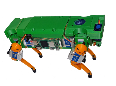
There are quite a few models in the Dynamixel range, from tiny to huge and powerful. I could claim to have done a thorough research to select the model with the most optimal parameters for my application. But in practice the decisive factor was price, so I went with the cheapest (and smallest) I could find and picked the XL330-M288-T.

It’s quite small, not much bigger than the cheap 9g servos I used before, and also light (18g). Unlike its bigger siblings, it only needs 5V for power and uses 3.3V for “TTL” serial comms – which makes it really easy to use with a Raspberry Pi. One drawback is the all-plastic construction (you’re supposed to attach things to the round plastic “horn” with self-tapping screws). Also, unlike bigger Dynamixels, this small one doesn’t have an idler horn (on the opposite side), which is not so great for arm joints.
Half-Duplex, Multi-Drop Serial
These servos can be directly connected to the Raspberry Pi’s serial pins (3.3V, with configurable baud rates) – so controlling them should be just a matter of understanding their protocol. But this is not “ordinary” serial:
- Half-duplex = a single wire for data (TX + RX), so only one device can talk at a time.
- Multi-drop = multiple devices attached to the same bus – so you can chain them together, which is particularly nice for many joints in a robot arm.
So we’ll only have three wires (5V, GND, DATA) from the Pi to the servo for our first joint, which in turn will be connected to the second servo with the same three lines, and so on. This means that we need some kind of switch between the RX/TX pins of the Raspberry Pi and the DATA line of the servos:
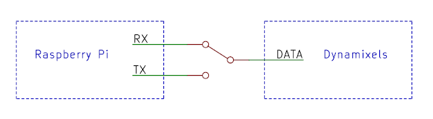
For example, when we send a command from a Pi, we’d connect TX to DATA, then switch to RX and listen for a response.
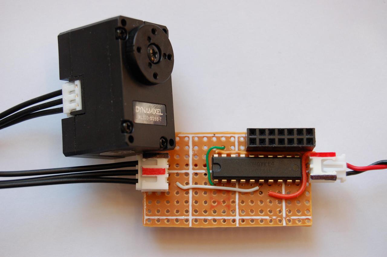
But of course, we need a digital switch, something we can control with an additional GPIO pin. The Dynamixel manual already includes an example schematic, using a 74xx241 “octal buffer and line driver” IC: this has two sections, with two “output-enable” inputs, with one of them inverted. By connecting these together and controlling them from an extra GPIO pin, we can easily implement our switch:
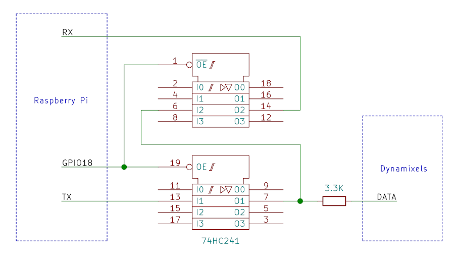
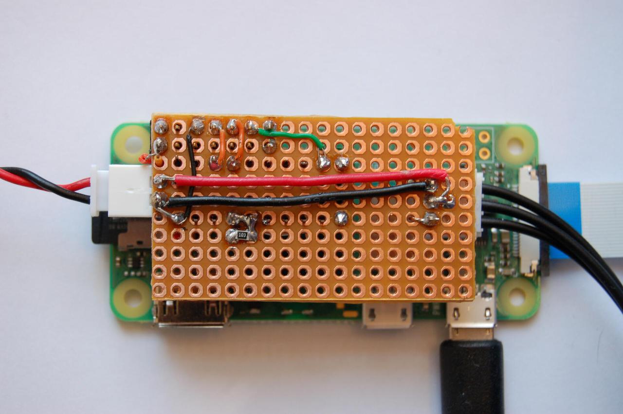
I made a prototype for this, a little “hat” that goes on top of the Pi (also has a pass-through 5V power connector):
(Robotis also makes a USB adapter dongle for Dynamixel servos to easily connect them to PCs: this takes care of converting “normal” serial USB on the PC side to half-duplex for the servos, and also supports RS-485 for more serious models. Using this would make things much easier, without the need for custom hardware. I decided not to use this for several reasons: 1) didn’t want to pay even more for another part, 2) wanted to avoid adding something relatively bulky to the robot, but most importantly 3) we need the USB port to have networking between the two Pi Zero 2’s on board Flig!)
Software – the Hardest Part
Now that the hardware is all sorted, all we need is some software to start talking to these servos – surely, this is easy! When doing my initial, superficial “research”, I’ve seen plenty of people using Dynamixels from a Pi with similar circuits like above, using a GPIO pin to toggle comms direction before/after sending serial data. The logic is really simple:
- Keep GPIO18 low by default (“RX mode”)
- Before sending data: turn GPIO18 high (“TX mode”)
-
write()command to servo(s) on serial - Turn GPIO18 back to low (“RX mode”)
-
read()response from serial
I’ve decided to use the official DynamixelSDK for low level control. (This should fit nicely into my whole software stack using ROS, with higher level, hardware-independent controller components using it – but more on this later…)
When I tried to use the SDK for real for the first time, I realised that it doesn’t support this “extra GPIO” scheme. At least not for the Pi or Linux: they recommend using the above mentioned USB dongle instead. But there is also an Arduino version of the SDK, which does expect to use an extra pin like we want – which makes perfect sense. So all that needs to be done is to add this extra feature to the Linux version of the SDK (and there was already a comment about this in Github, with very useful pointers to the Arduino code).
So I went on to read the SDK code to understand better how exactly it uses serial, learnt about libgpiod, and soon enough figured out how to make the necessary changes. After double-checking all the wiring I connected everything together, started a little test program to make a single servo turn, and then… nothing!
What followed was roughly this:
- Double-, triple-checked the wiring again – still nothing.
- Discovered some stupid mistakes I made in the code, fixed them and tried to tweak some timings, added some debug output – nothing.
- After some more thinking I realised the obvious fact that serial comms and toggling a GPIO pin in a non-real-time environment (unlike a microcontroller) is not quite straightforward: there is no guarantee that reading/writing to a serial port and toggling a GPIO before/after happens in an exact, neat sequence like above: most things are asynchronous by design and involve potentially multiple buffers that might need to be flushed, etc. So when the
write()call returns, there is no guarantee that all the bytes have actually been sent over the wire. If we switch back to “RX” right away, we might cut off some of the data being sent! I read a bit more and discoveredtcdrain()– which seemed exactly what I needed (“waits until all output written to the object referred to by fd has been transmitted”). So: 1. switch to TX, 2.write(), 3. calltcdrain()to wait for the write to finish, 4. switch back to RX, 5.read()the response. - And with that, I finally managed to make the servo turn once! (And after a bit more tweaking, I could make it turn more than once, almost reliably!)
- However I noticed that the position apparently reported back by the servo was always 0 – I thought this was just a small mistake somewhere, must be easy to fix, as I could control the servo now, it was clearly following the given position correctly.
- After some more experimenting and digging into the SDK code, I realised something worrying: I actually never get any response back from the servo! So I can talk to it, but I never hear back from it!
- More research, more reading, more digging into the code – but all I found was some more obscure/potential bugs everywhere… but nothing directly relevant.
- I checked the circuit again, to make sure the RX path was wired correctly. I also added a capacitor – surely that can never hurt!
- In a final desperation I even added three LEDs to the circuit and tried to catch rapid blinks to determine whether the RX/TX/OE lines were actually active at the right times.
- Then I tried to search for any mentions of half-duplex serial comms in Linux in general, hoping for some clues, any clues at all. Then I finally stumbled upon some obscure, not entirely related posts in a forum about problems with
tcdrain()waiting for too long. It does correctly wait until all output has been written – but that doesn’t mean that it returns immediately after the write has finished! If it waits a bit longer, then by the time it returns, we might miss the response coming back from the servo! Obviously we can’t switch from TX to RX too early, but we also shouldn’t switch too late! - So finally, I replaced the
tcdrain()call with a precisely timedwait()– based on the baud rate and the number of bytes we’re sending. - IT WORKED!!!
So it looks like a happy ending, after a long, tedious and mostly clueless series of attempts. There was one final hurdle though…
Having established that I could control a single servo reliably, I went on to chain together more of them – it was still fine! Then I tried controlling a few joints “for real”, using ROS controllers with a higher level “driver” on top of the SDK. It’s essentially a continuous loop running at a fixed frequency that constantly queries the current positions of all servos and sends them goal positions. So it’s not doing anything different from my tests before, it’s just doing it all the time – and of course doing some other things like talking over the network, logging, etc.
It seemed OK at the first try, but then as I tested it for longer, read errors started happening randomly. A few of these are not necessarily catastrophic: if our loop is running with a high enough frequency, occasionally missing a few reads won’t make any difference. But as I tried to increase the frequency, the errors became more frequent too. And what was really worrying is that sometimes (actually quite often!) read errors happened at the beginning, when the process was starting and tried to ping the servos to check the connection – when these reads fail, that is a serious error, it means I can’t reliably start the process!
This time around, I was a bit less clueless: the appearance of the errors clearly correlated with the system load – the whole startup sequence actually involves starting some other processes at the same time, so the CPU was always a bit busier at the beginning. And because we’re not in a synchronous, real-time system, our process can be interrupted any time, slightly delaying reads or writes or any carefully calculated wait() calls, breaking this whole illusion of precise control we might think we had.
That’s great for explanation, but how can we get rid of these errors? Switching to a real-time kernel may or may not be possible, but it’s certainly something I didn’t want to even think about. Can we simply increase the priority of our process to make it less interruptible?
There is setpriority() or (nice): we can set the priority of our process to the “most favourable” value, -20. That’s great, but it didn’t seem quite enough.
There is more however, another “level”: changing the scheduling policy. This is basically a way to assign processes to different categories for the kernel scheduler. Ordinary processes all run under the same SCHED_OTHER policy by default. Changing this to SCHED_FIFO puts our process into a “real-time” category, always giving it more priority than others. It also comes with its own range of priorities – and using this can actually be dangerous, as a runaway infinite loop that never sleeps can starve the rest of the system. We can change the policy by calling sched_setscheduler() or by starting the process with chrt command. (And to enable all this we also need to add an entry for rtprio to /etc/security/limits.conf.)
This finally made everything usable: read errors still happen very rarely, so this will never be a 100% perfect solution, but I think this is the best you can do to talk to hardware from outside the kernel.
Comments
Comments powered by Disqus